
Author: Dr. Augusto César Bessa Neves
40-year-old male patient.
CHIEF COMPLAINT
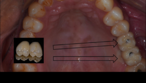
Dissatisfaction with the absence of elements 26 and 27.
INITIAL EVALUATION
After detailed anamnesis, clinical and radiographic examination, the absence of elements 26 and 27 was noted, and, it was also noted that topographically, there was a pneumatization of the maxillary sinus floor.
TREATMENT CARRIED OUT
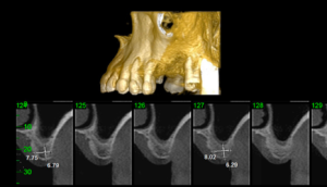
Since the tomographic exam showed 6.79mm and 6.29mm remaining bone of the areas of elements 26 and 27 respectively (fig. 1), the plan made was to apply the surgical technique to lift the maxillary sinus SA3 described by Carl Misch et al. According to that technique, the lifting of the maxillary sinus floor is carried out at the same time of the installation of dental implants. In order to have access to the maxillary sinus, we used a surgical drill (Fig. 2), with the purpose of achieving more preciseness in the osteotomy (Fig. 3). Working in a surgical site with low density and knowing that the geometry of the drills allows for single drilling, we chose that technique for the perforation of the surgical sites (Fig. 4). The tridimensional positioning of the implants must be perfect and, therefore, it is important to carry out an adequate reverse planning, working with a surgical guide and, in the trans-operatory phase, always verify parallelism, using
the posts appropriate for that function (Fig.5). Afterwards, the L-PRF BLOCK was carried out associating FGM’s Nanosynt with particle granulations between 500 and 1000μ to the platelet aggregate, inserting it to the maxillary sinus (Fig. 6). Following that, implants were installed in the surgical sites and L-PRF membranes were inserted in the lateral wall of the maxillary sinus before suture (Fig. 7 and 8).
4 months later, the healing abutments were removed (Fig. 9) and the transmucosal height measurer tool was positioned to select the mini abutments (Fig. 10). Then, those intermediate abutments were installed using the abutment placement tool (Fig. 11). Molding was then carried out (Fig. 12) and the plaster was applied (Fig. 13) and sent to the laboratory. In the laboratory, the plaster model was converted to a digital model, transferring the position of the implants by means of the Arcsys Scan Body, followed by a digital flow for the manufacture of the crowns over implants (Fig. 14). The crowns were finalized and installed on the implants (Fig. 15).
STEP-BY-STEP
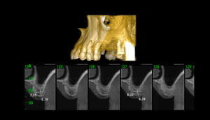
Fig. 1 – Tomography in the pre-operative phase.

Fig. 2 – Neurological phase for the access to the maxillary sinus.
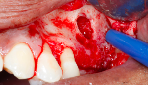
Fig. 3 – Precision in the osteotomy with the use of the surgical drill.

Fig. 4 – Surgical site with good recommendation for single drilling.
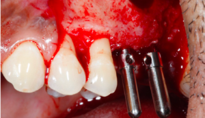
Fig. 5 – Checking parallelism.

Fig. 6 – L-PRF-BLOCK carried out with Nanosynt.

Fig. 7 – Arcsys implants being inserted.
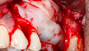
Fig. 8 – Membranes of L-PRF on the side wall of the maxillary sinus.
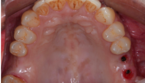
Fig. 9 – 4 months later, healing abutments are removed.
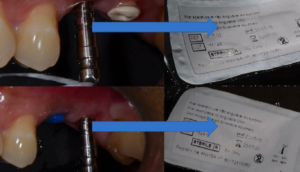
Fig. 10 – Transmucosal height measurer tool positioned for the selection of the mini-abutments.
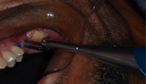
Fig. 11 – Abutment placement tool activating the mini-abutments.
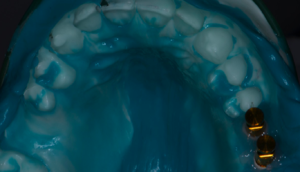
Fig. 12 – Molding.
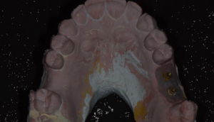
Fig. 13 – Plaster applied before shipment to the laboratory.
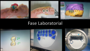
Fig. 14 – Plaster model converted into a digital model.
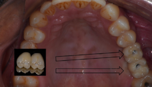
Fig. 15 – Crowns on implants are installed.


